|
Cooling System Configurations
Each generator set manufacturer offers different options for design of the cooling system. The two most common styles of cooling systems are closed loop and open loop systems. Closed loop systems incorporate cooling pump(s), cooling fan and radiator(s) located on a skid as an all in one unit. In addition, container and trailer options are offered.
An ethylene glycol based coolant is circulated through the cooling system components. Three common cooling system configurations are:
Single Pump Single Loop (SPSL) – SPSL systems are common in smaller to mid-size generator applications. Operation for this system as follows:
• Engine starts, direct drive pump is driven and fan clutch is rotating.
• Engine reaches operating temperature, coolant thermostat opens and fan clutch engages.
• Ethylene glycol coolant is supplied to engine block and cylinder head internal components, such as oil cooler and intercooler.
• Air is pulled through the radiator.
• Return coolant flow is directed to radiator.
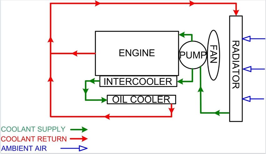
Figure 1, SPSL Cooling System Configuration
Double Pump Double Loop (DPLP) – DPLP cooling system configurations are common to large generators and when a generator is located in a high ambient temperature atmosphere. Operations for this system as follows:
• Engine starts, direct drive pump is driven and fan clutch is rotating.
• Engine reaches operating temperature, coolant thermostat opens and fan clutch engages.
• One pump routes ethylene glycol coolant to engine block and cylinder head.
• Remaining pump routes ethylene glycol coolant to internal components, such as oil cooler and intercooler.
• Air is pulled through the radiator.
• Return coolant flow is directed to the individual radiators.
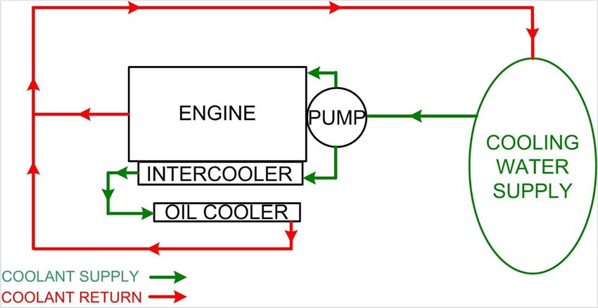
Figure 2, DPDL Cooling System Configuration
Open Loop (SPSL) – Open loop systems are generally used in marine applications, although could be used where any acceptable body of water is available. Operation for this system as follows:
• Engine starts, direct drive pump is driven supplying seawater to thermostat.
• Engine reaches operating temperature, seawater thermostat opens and allows seawater flow through engine block, cylinder head and components such as oil cooler and intercooler.
• Return seawater is routed back to source.
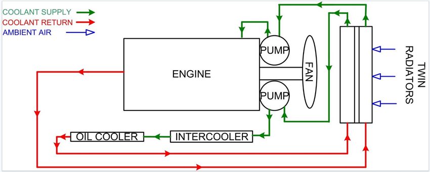
Figure 3, Open Loop (SPSL) Cooling System Configuration
Maintaining Cooling System
To insure generator performance, a basic understanding of cooling system components is required. Individual generator manufacturers publish inspection and maintenance procedures for the cooling systems. Below are general industry standards (always refer to manufacturer specifications):
WARNING
To prevent the possibility of personal injury or death, always tag and lock out all sources engine/generator power prior to cooling system maintenance.
Do not remove the pressure cap from a hot engine. Wait until the cool and temperature is below 120°F (50°C) before removing the pressure cap. Heated coolant spray or steam can cause personal injury.
Coolant is toxic. Keep away from children and pets. If not reused, dispose of in accordance with local environmental regulations.
Do not straighten a bent fan blade or continue to use a damaged fan. A bend or damaged fan blade can fail during operation and cause personal injury or property damage.
Caution
The cooling system must be filled properly to prevent air locks. If air exists in cooling system, pump will experience cavitation causing premature pump wear and engine damage. Always refer to manufacturer’s manuals when servicing cooling systems.
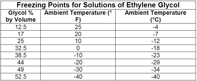
Coolant – Engine coolant is a mixture of clean good quality water and an ethylene glycol antifreeze mixture. Never run water only as a coolant. Coolant lubricates the coolant pump bearings and aids in protection from rust buildup in the engine coolant passages. Always refer to manufacturer’s recommendations for proper coolant mixture. Below is a table to aid in mixing coolant to manufacturer’s specifications.
Coolant System – Each generator application can have a different cooling system configuration. Below is a general list of components:
• Coolant pump – Depending on engine size, belt or gear driven. Circulates coolant throughout cooling system.
• Radiator – Can be single or twin radiator design. Using two radiators to allow for two loop system allows for greater cooling capability.
• Fan – Can be belt or direct drive. Belt driven applications can use a fan clutch to allow for as needed fan engagement.
• Engine Oil Cooler – Coolant supplied to vessel. Vessel has a bundle of tubes that is immersed in coolant. Oil flows through tube bundle and is cooled by surrounding coolant.
• Intercooler – Coolant is supplied to a tube and fin bundle. Tube and fin bundle is located in a vessel. Air flows through vessel and is cooled by tube and fin bundle.
• Louvers – Used in canopy and mobile units to allow air to flow to the radiator from atmosphere. Control systems can allow for full open or full close. Advanced control systems can allow for louver to open as much as required for premium operation.
Cooling System Inspection – General cooling inspections should be completed during generator down time and while generator is in operation. Manufacturer’s recommendations always should be followed. Below are some minimum checks that can be used when recommendations are not available.
During Shutdown:
• Leak at water pump(s) weep hole.
• Damage, leaks and debris in radiator(s) fins.
• Coolant level and oil contamination. Oil in coolant could indicate leaking oil cooler bundle.
• Coolant specific gravity.
• Damage to fan, fan shroud or belts.
• Coolant leaks at hose connections.
• Oil for evidence of coolant contamination. Milky color could indicate leaking cylinder head gasket.
• Louvers should be closed during periods when generator is not in operation.
• Automatic transfer switch in correct position.
During Operation:
• Engine coolant temperature.
• Prior to coolant reaching operating temperature, make sure fan is not spinning on fan clutch applications.
• When coolant reaches operating temperature, make sure fan is spinning on fan clutch applications.
• Coolant leaks at radiator.
• Coolant leaks at hose connections.
• Coolant vapor in engine exhaust. Indicates coolant leaking in combustion chamber.
|